Catalogue · Prices excl. VAT and postage
Products
Equipment of our own manufacture for surface mounting, measurement, soldering training and small-batch production. Prices are indicative.
Equipment of our own manufacture
10 itemsOther electronic novelties
Small setsAll types of equipment are low-priced and high quality. They are predominantly intended for user-friendly applications and production, optionally for training purposes. If the product is in stock, it can be delivered immediately; otherwise within approximately two months.
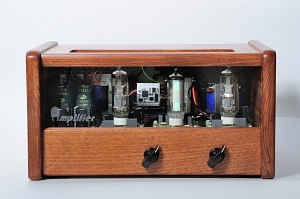
ELZES 2x5a vacuum-tube amplifier
Product detailAfter the rise of semiconductors, vacuum-tube amplifiers have kept their place — thanks to their specific characteristics and the so-called "tube sound" — as guitar amplifiers for musicians. The transistor is a current-controlled semiconductor device, whereas the tube is voltage-controlled; the frequency spectrum, especially at overload, differs accordingly.
This is a stereo vacuum-tube amplifier, using a modified circuit from the Tesla 4243–Spoletto television set produced in the 1980s. The amplifier is fitted with a fluorescent level indicator and a modern Bluetooth module.
Operation and construction
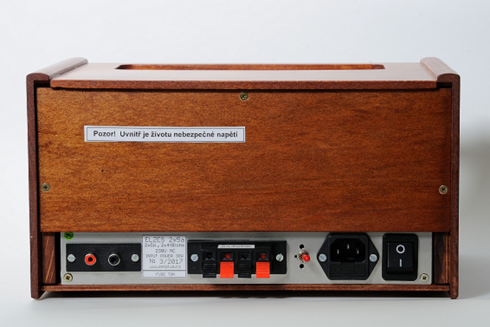
The amplifier has two identical low-frequency channels rated 2 × 5 W. Instantaneous output and modulation are shown by a strip indicator. Gain is regulated by two independent potentiometers. The LF signal can be connected via CINCH (RCA) connectors, or wirelessly via Bluetooth (e.g. from a mobile phone). When Bluetooth is inactive for 5 minutes the amplifier enters standby with minimal consumption. Since the circuit runs in Class A, consumption is around 30 W even without signal. The unit is housed in a solid-wood cabinet with a glass front panel that allows a view of the glowing tubes during operation.
Technical specifications
- Output power
- 2 × 5 W p-p
- Load impedance
- 4 Ω · 8 Ω (switchable)
- Input impedance
- 50 kΩ
- Input sensitivity
- 0.7 V for 4 W
- Frequency response
- 40 Hz (−1.2 dB) – 40 kHz (−1.8 dB), Up-p = 1.88 V / 1 kHz, 4 Ω
50 Hz (−0.5 dB) – 30 kHz (−0.3 dB) - Consumption
- 30 W · 1 W standby
- Tubes
- 2 × PCL86 · 1 × EM87
- Bluetooth module
- KRC-86B V4.0
- Dimensions (L × W × H)
- 300 × 200 × 160 mm
- Weight
- 5.6 kg
- Housing
- Solid-wood cabinet, glass front panel
- Price
- 11,900 CZK (excl. VAT)
Reported by Ass. Prof. Ing. Josef Šandera, Ph.D. — updated 07/2018
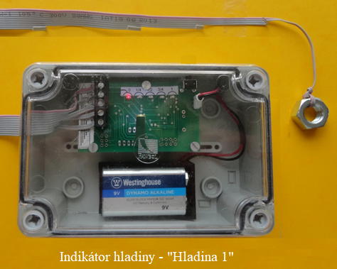
HLADINA1 liquid-level indicator
Product detailThe main principles for measuring all types of liquids and bulk materials are:
- mechanical level gauges,
- hydrostatic level gauges,
- electronic level gauges,
- pneumatic level gauges.
We manufacture a simple battery-powered device that measures the level of water and other electrically conductive liquids in four steps. Its strength is the simple sensor design that can be easily adapted to different heights. The device needs minimal maintenance — depending on liquid contamination, the measuring cable is to be cleaned.
Electronics and sensor overview
Operating on the principle of electrical conductivity, the device can indicate the level of non-flammable liquids in water wells (for utility or drinking water), septic tanks, water reservoirs for caravan irrigation and other equipment. The indicated liquid must exhibit electrical conductivity.
The indicator must not be used to measure hazardous or flammable liquids. Further details are in the manual (PDF, CZ).
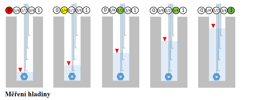
Using the indicator
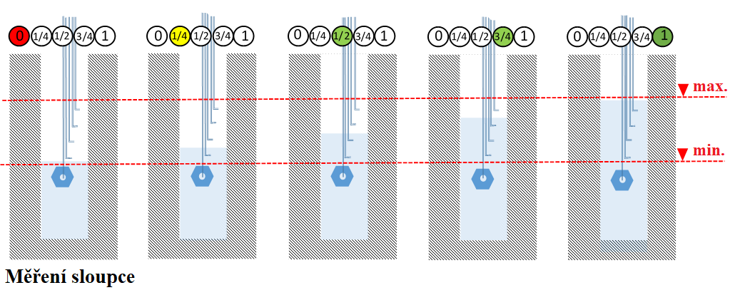
The following figures show the available measuring options. The reading in the circle indicates the indicator's state. To read the actual level (and thus the liquid quantity), the probe is placed with the weight on the tank bottom. To monitor only the minimum and maximum levels, the probe is placed as shown in the second figure.
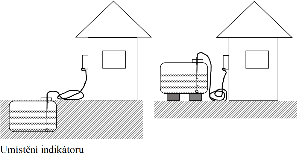
Indicator placement
Outdoor placement options:
- installation in an above-ground tank,
- installation in an underground tank.
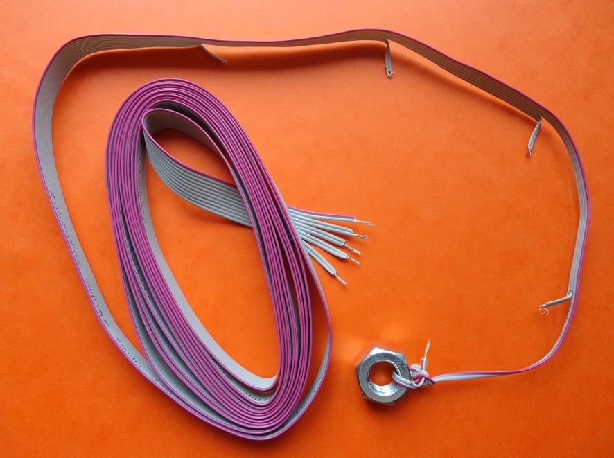
Probe construction
The probe end is screwed into the terminal block on the device. The wire insulation is stripped over 10 mm in length and twisted (optionally soldered) in pairs. Branches at defined positions are formed by pulling apart and cutting a pair of leads to the required length and stripping about 5 mm of insulation (do not modify the ends). On the last pair (one wire is marked red), an M12 nut is tied on as a weight.
If the sensor needs to be installed at more than 30 m (supplied cable length), use an additional length of the same ten-wire AWG28-10H cable. A total length of 60 m has been tested without problems. Use a screw terminal block to extend; the connection must be kept dry.
Sizing the probe
- Measure the liquid height from the tank bottom (using a stick or rope).
- Divide the height into quarters and place measurement taps at those positions. Tie an M12 nut to the last pair (the red-marked wire) as a weight; remember to strip about 5 mm at the end of the lead pair.
- Suspend the probe so that the weight rests on the bottom (Monitoring the level).
- To monitor only the minimum and maximum levels, measure the maximum and minimum levels.
- Divide that span into quarters, place taps and tie the M12 nut at the end.
- Suspend the probe so that half of the measurement range is at the expected (mid) level — Monitoring a defined column.
Detail images
Maintenance
If several levels light up at once, remove the probe and clean the measurement taps. The cleaning interval depends on the nature of the liquid — typically around six months. Wipe the probe with a rough surface (a kitchen sponge works well). Battery life depends on reading frequency — practically up to several years. Otherwise the indicator needs no maintenance.
Reported by Ass. Prof. Ing. Josef Šandera, Ph.D. — updated 03/2022